Mining Methods
There are four key stages of work involved in mining for minerals. These include: 3415 , 3416
- Prospecting – The purpose of this stage is to identify areas that are likely to contain mineral deposits. The work includes geological, geochemical and geophysical surveys (e.g. seismic surveying), aerial surveys, including the taking of samples by low-impact mechanical methods. 3417 For example, in the marine environment, multibeam swath bathymetry can be used to map the seafloor, and Remotely Operated Vehicles or submersibles can be used to collect images of the sea floor, take core samples of the seabed at low concentrations, and collect targeted samples.
- Exploration – The purpose of this stage is to discover potentially mineable resources and evaluate the feasibility of mining identified deposits. This stage can include any drilling, dredging or excavations needed to assess the nature and size of a mineral deposit. 3418 The exploration phase may involve core sampling at higher concentrations (than undertaken in the prospecting phase) in small areas, test pit excavation, test drilling, trials of extraction methods and bulk sampling. This exploration could involve the removal of larger volumes of deposits.
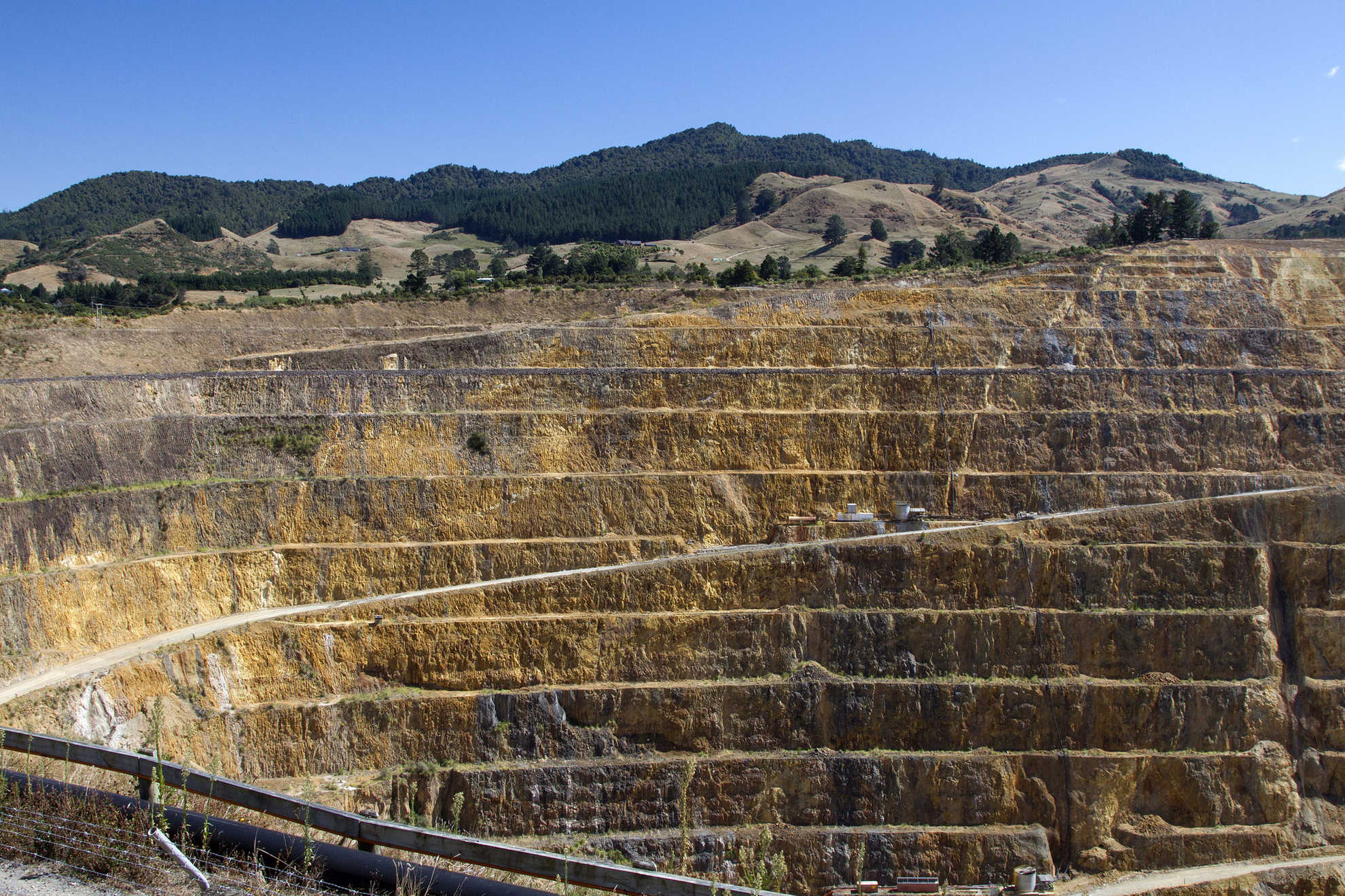
- Production – The purpose of this stage is to actively extract and process the mineral resource. Minerals in the terrestrial environment may be mined using underground or open cast methods. Open cast mining is used in situation where the minerals are relatively shallow or less concentrated. Underground mining is used for deposits at greater depth, higher grade deposits, or vein ores. Underground mining is more expensive, but less environmentally destructive. 3419 Techniques which may be utilised include blasting, excavators, and, in the case of underground coal mines, high-pressure water cannons. 3420 Techniques for mining minerals in the marine environment may involve seafloor suction dredging, seafloor slurry pipes, use of tracked vessels on the seafloor and seafloor cutting/fragmentation. Following extraction and processing, tailings (unwanted material) are deposited back onto the seafloor. Some production operations involve a processing vessel that moors to "permanent” anchor blocks or anchor moorings.
- Rehabilitation – The purpose of this stage is to restore the area following the conclusion the mineral production. Techniques will vary depending on the mining that has occurred, the location of the mining and the desired future use of the area.
Due to the high variation in the geological processes governing resource formation and concentration associated with the different mineral deposits, and their engineering and geotechnical characteristics there is no single, universal method which can be deployed. A variety of methods will be required to mine minerals deposits. Technology that can be used to mine minerals from the seabed efficiently in deeper waters is only just being developed, and work is still ongoing to determine what the most effective methods of mining may be, both in terms of resource recovery and for minimising environmental impacts.
Types of Seabed Mining
The following sections describe mining methods for particular mineral types in more detail:
Phosphate
Mining for phosphate generally requires a mining vessel that deploys a trailing suction drag-head that moves along the seabed. Water jets and possibly cutting teeth are used to loosen the top centimetres of seabed sediment, and the resulting slurry of sediment and seawater is pumped to the mining vessel. The material will be mechanically processed on-board the ship to separate the coarse phosphatic material from the finer non-phosphatic sediments. The fine non-phosphatic sediment and seawater will be discharged to the seafloor or above the seafloor.
3421
Chatham Rock Phosphate Ltd (CRP) proposes to mine phosphorite nodules from the crest of Chatham Rise, about halfway between Banks Peninsula and Rekohu/Chatham Islands. The company has a mining permit for 820 km2 on the crest of Chatham Rise. It also holds two prospecting licenses for surrounding areas. The process that the company is proposing for the mining operation is discussed further in the case study.
Seafloor massive sulphides
Seafloor Massive Sulfide deposits form in submarine volcanic regions where sulphur-rich magmatic and hydrothermal fluids precipitate sulphur and metals around hydrothermal vents. The hydrothermal fields typically occur on mounds that contain mineral precipitates and both high temperature ‘black smoker’ vents and lower temperature diffusive venting. Where mineralization is extensive SMS deposits can form, consisting of economically viable reserves of Cu, Pb and Zn, with some deposits also rich in Au and Ag. 4564
In the New Zealand EEZ and Extended Continental Shelf (ECS), hydrothermal venting is known to occur on two-thirds of the 30 Kermadec Arc volcanoes 4565 but only two sites, Brothers and Rumble II West, are so far reported to host SMS deposits of commercially exploitable scale. Deposits may also occur elsewhere in the Kermadec arc – Havre Trough volcanic system, although no hydrothermal activity has been found in the Havre Trough or on the Colville and Kermadec Ridges, which represent the proto-Kermadec arc. 4566 However, the small number of known SMS deposits may simply be the result of the limited exploration of these areas.
- Identifying potential targets
- Testing potential targets and delineating prospects
- Evaluating the resource
- Extracting minerals from the seafloor using remotely operated mining equipment
- Transporting the ore, via a lifting system, from the seafloor to a production support vessel at the water surface
- Dewatering the ore on-board a production support vessel or platform
- Transferring the ore from the production facility to a transport barge or bulk carrier
- Transporting the ore to land for treatment and/or processing
- Transporting concentrate and saleable products to market
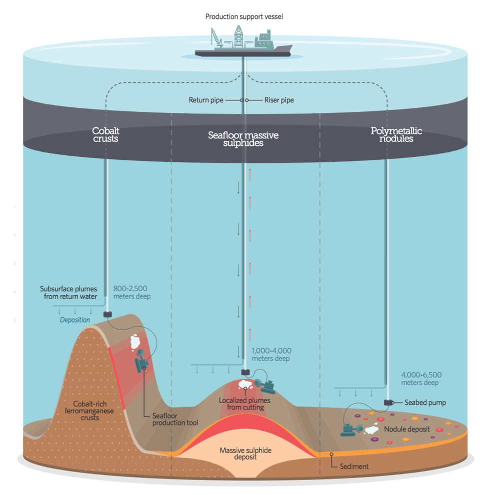
Currently the only model for SMS mining is that proposed by Nautilus Minerals Limited at Solwara 1, a high-grade copper-gold mining project which is located 30 kilometres off the coast, and about 1600 metres deep, in the territorial waters of Papua New Guinea. 3423 This company proposes to use a “Seafloor Mining Tool”, envisioned to be a large tracked Remotely Operated Vehicle, incorporating tools for cutting up the vent chimneys and hydrothermal deposits, and suctioning the material to a Mining Support Vessel at the surface (see figure below). 3424 The ore will be dewatered on the vessel, and transferred to a barge for transport to shore for processing.
Manganese nodules and cobalt crust
Manganese nodules sit on a soft-sediment surface, and can be recovered by dredging through trawling or by suction. There is currently no known active extraction of manganese nodules anywhere in the world. 3425 Since 2001 several permits have been issued to governmental institutions and private companies by the International Seabed Authority to survey manganese fields. These permits are not for mining, but for a detailed initial investigation of the potential mining areas. In 2013, several companies also submitted applications for the exploration of manganese nodule fields in the high seas in cooperation with developing countries (Kingdom of Tonga and Republic of Nauru). 3426 There is now interest in manganese nodule fields inside the EEZ of countries such as the Cook Islands.
Exploration and mining of manganese nodules and cobalt crusts are expected to involve the following basic processes:
3427
- Recovery of minerals from the seafloor using remotely operated sea-floor production equipment
- Transport of a slurry (ore and seawater) vertically from the seafloor to a vessel or platform on the sea surface
- If substrate rock is collected, separation of ore and gangue (the material in which ore is found that has no economic value) using froth flotation on board a vessel
- De-watering of the ore on board a vessel or platform
- Transfer of the ore from the vessel to a transport barge or bulk carrier/storage facility
- Disposal of the separated seawater
Technologically, the mining of cobalt crusts is considerably more complex than that of manganese nodules, as the crusts form a hard substrate. Ideally, a mining operation would only remove the crust, and not the underlying volcanic rocks. In addition, the slopes of the underwater volcanoes where the crusts are located are very rugged, which can make the use of excavation equipment more difficult. Cobalt crust mining is only at the conceptual stage at present. It is believed that the greatest barrier to mining both manganese and cobalt resources is the processing stage and how to viably process the ore to extract the minerals once it has been removed from the seabed.
Methane hydrates
Mining for methane hydrates is still in its early stages. In March 2013 a Japanese company became the first to extract gas from offshore methane hydrates. It is aiming to commence commercial production by early 2019.
3428
In 2008, a joint Canadian-Japanese expedition in Mallik in the Northwest Territories, Canada, established that methane hydrates could be collected by using a water pump to de-pressurise a well already drilled. This process involved lowering the pressure by pumping out the water that naturally accumulates in the well. Standard oil and gas drilling equipment was used to re-enter the existing well drilled to a depth of just over 1000 metres and then to “refurbish” it by casing the entire well with lengths of steel tubing cemented into place to prevent it from collapsing. 3429
Subsequently, gas hydrate resources on the Alaskan North Slope have been classified as technically recoverable, and the first production tests offshore in Japan suggest production of gas from offshore hydrates is now also technically feasible.
3430
Exploitation in New Zealand remains a major challenge for a number of factors:
3431
- The logistical cost of exploration is high because of the offshore location of potential resources
- New Zealand’s geology is complex, meaning the geological parameters such as source rock, migration pathways and reservoir rock are highly variable, both within a basin and between a basin
- New Zealand has few exploration wells to date, so that the volumes of undiscovered methane hydrate reserves are difficult to predict
- The methane hydrate is under immense pressure, thus there are significant concerns about being able to bring the resource safely to the surface
Sand mining
Prospecting generally involves reconnaissance drilling to recover sediment samples for analysis onshore, airborne geomagnetic studies and seismic surveys, as summarised in the table below. 3432 A limit on the volume of sediment which can be removed, and on the total number of core samples which can be taken, is normally set in the prospecting permit. For example, the Trans-Tasman Resources Limited prospecting permit sets a limit of 600 cores in total over an area of 6319 square kilometres. The intensity of sampling will typically increase when the exploration phase starts.
Method | Summary |
|---|---|
| Boat-towed magnometer systems |
|
| Vibracore sampling |
|
| Reverse circulation sampling |
|
| Sonic drilling |
|
| Side-scan sonar and multi-beam sonar |
|
| Low frequency echo sounder |
|
Active mining of the seabed is generally undertaken using suction pipes to pump sand that has been mixed with seawater from the seabed. Iron ore is magnetically separated from the sand, whilst other minerals are extracted by sieving, before returning the residue back to the sea. 3442 The sand mining methods used will vary, depending on the depth of the seafloor where the sand is being extracted from, and the distance from shore.
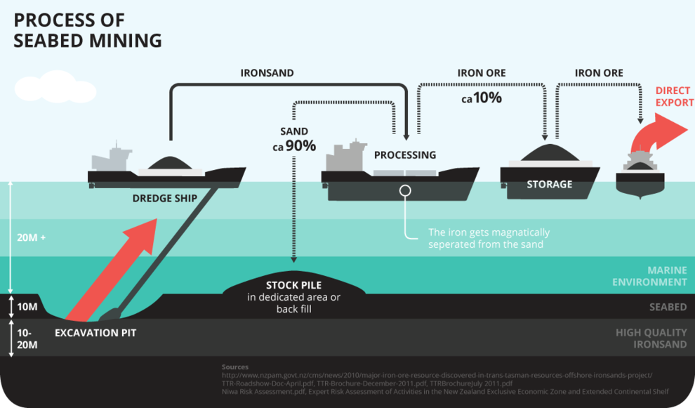
Trans-Tasman Resources Limited applied to mine iron sands in the South Taranaki Bight using a subsea sediment extraction device called a “Crawler”. This would create a mining cut approximately 12 metres wide and up to 11 metres deep. The seabed material would then be pumped by a slurry delivery pipe to a “Floating Processing Storage and Offloading Vessel” where it would be processed to separate the iron ore (approximately 10 per cent yield). Processing would involve screening to remove material greater than two millimetres in size, and grinding and magnetic separation. The de-ored sand would have been re-deposited into areas which had been mined. 3445 The iron ore concentrate would be transferred to a “Floating, Storage and Offloading Vessel” where de-watering and storage would occur. It would then be transferred to bulk carrier vessels for export.
Different methods are used for inshore mining, depending on the location of the sand resource. For example, at the Waikato North Head mine site, the iron sand is processed at an on-site concentration plant, where a magnetic concentrate is extracted through a series of separation processes producing a slurry. The slurry is pumped to the Glenbrook Mill through an 18 kilometre long underground pipe. Fresh water used during this process is drawn from a lagoon adjacent to the Waikato River. The by-products from these processes are used for site rehabilitation after they have been dewatered.
3446
At the Taharoa mining site, sand is extracted from a pond by a floating dredge and then, because the area has no natural harbour, pumped as a slurry to a bulk cargo ship moored three kilometres from the shore plant to be processed and then exported. 3447 Between 200 and 300 tonnes of magnetic concentrate is produced per hour. 3448 The removal of sand from the Mangawhai-Pākiri embayment is generally completed using a suction dredge. This is typically a rotary cutter suction dredge, where a rotating head disturbs the sediment, allowing it to then be entrained into the inflow of the suction pipe. Sand is then screened using mesh sizes of 3 millimetres, which removes gravel, shell and debris.
-
NIWA, 2012
-
Ministry for the Environment, 2012
-
Crown Minerals Act 1991, section 2(1)
-
Crown Minerals Act 1991, section 2(1)
-
Parliamentary Commissioner for the Environment (September 2010) Making difficult decisions: mining the conservation estate
-
Michelle Van Kampen The Adequacy of Legislation Regulating the Environmental Effects of Mining in the New Zealand Journal of Environmental Law Volume 16 (2012) at page 203
-
NIWA, 2012
-
Secretariat of the Pacific Community, 2013A
-
http://www.nautilusminerals.com/s/Projects-Solwara.asp
-
Collins P C et al., 2013
-
Collins P C et al., 2013
-
Bollmann M et al., 2010
-
Secretariat of the Pacific Community, 2013B and 2013C
-
http://www.worldenergy.org/wp-content/uploads/2013/10/WER_2013_3_Natural_Gas.pdf
-
http://www.technologyreview.com/news/413730/mining-ice-that-burns/
-
http://www.gns.cri.nz/Home/Our-Science/Energy-Resources/Gas-Hydrates/Current-Research/Gas-hydrates-as-an-energy-resource
-
Funnel R, et al., 2009
-
Thompson K, 2012
-
Badesab F, et al., 2012
-
https://www.niwa.co.nz/our-science/freshwater/tools/kaitiaki_tools/land-use/mining/activities
-
http://www.epa.govt.nz/Publications/TTR_Impact_Assessment_Summary_FINAL_21_October.pdf
-
http://www.nzsteel.co.nz/new-zealand-steel/the-story-of-steel/the-mining-operations/waikato-north-head-mine-site/
-
http://www.ipenz.org.nz/heritage/itemdetail.cfm?itemid=134
-
http://www.nzsteel.co.nz/new-zealand-steel/the-story-of-steel/the-mining-operations/taharoa-mine-site/
-
De Ronde et al. 2007.
-
De Ronde et al. 2007.
-
Wysoczanski and Clark 2012.
Last updated at 5:37PM on January 9, 2018